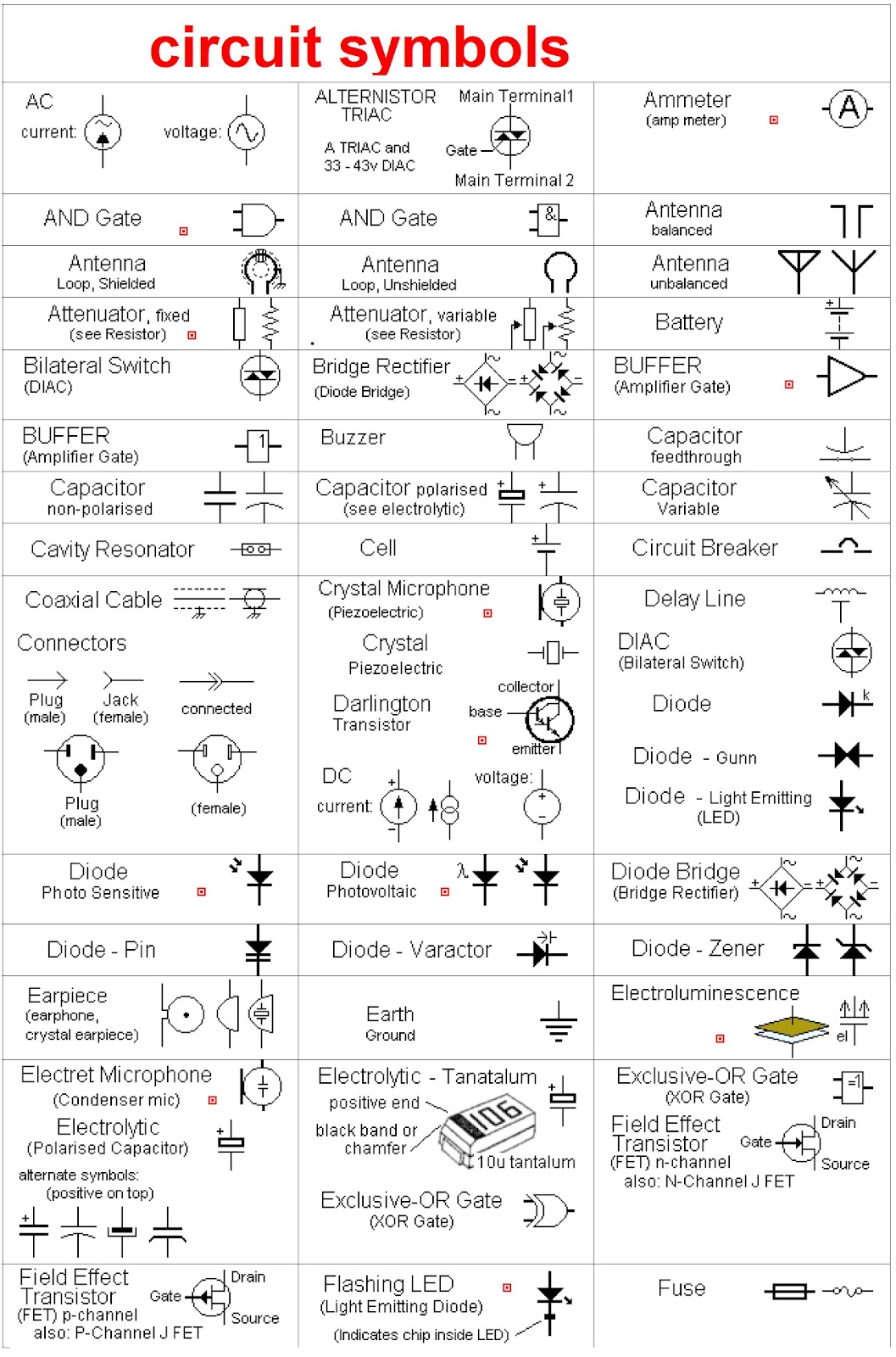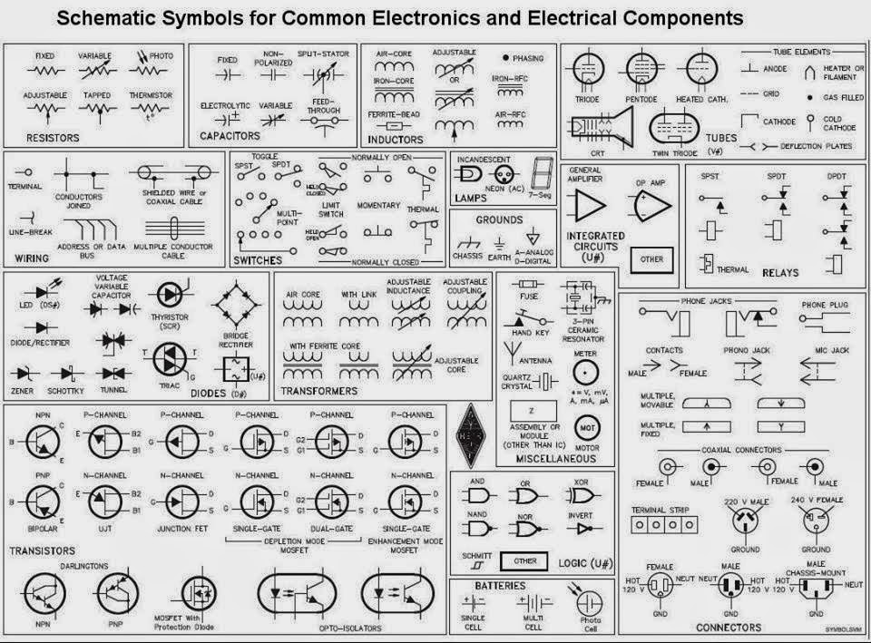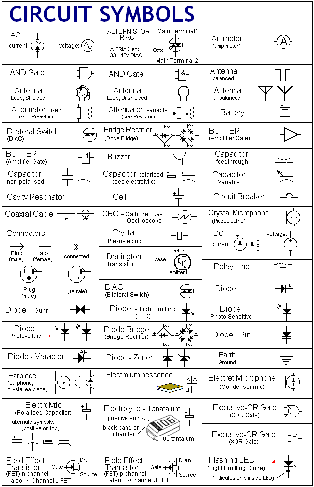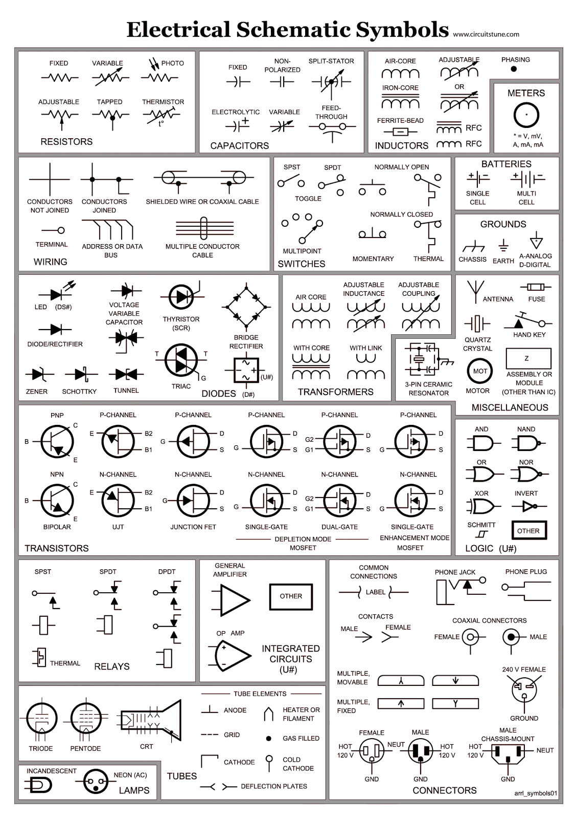
Ever wondered how complex electronic circuits are designed and understood? The answer lies in a universal language: electronic schematic symbols. These visual representations are the building blocks of electronic design, enabling engineers and hobbyists alike to communicate and collaborate effectively. From simple resistors to intricate microcontrollers, each component has a unique symbol that conveys its function and characteristics within a circuit.
Understanding electronic symbols is essential for anyone working with electronics. They allow us to decipher complex circuit diagrams, troubleshoot malfunctions, and even design our own electronic creations. This guide will delve into the world of electronic schematic symbols, exploring their history, significance, and practical applications.
Imagine trying to describe a complex circuit using only words. It would be a confusing and inefficient process. Electronic schematic symbols provide a concise and standardized way to represent electronic components and their connections. This visual language simplifies complex designs and makes it easier to analyze and understand how circuits work.
The evolution of electronic schematic symbols is intertwined with the development of electronics itself. Early symbols often resembled the physical components they represented. As technology advanced, symbols became more abstract and standardized, allowing for greater clarity and universality across different fields and regions.
Standardization is key to the effectiveness of electronic schematic symbols. Organizations like the Institute of Electrical and Electronics Engineers (IEEE) and the International Electrotechnical Commission (IEC) have played a crucial role in establishing globally recognized standards for electronic symbols. This ensures that engineers and technicians worldwide can interpret circuit diagrams consistently and accurately.
The history of electronic schematic symbols reflects the progression from simple circuits to complex integrated systems. Early symbols were often pictorial, resembling the physical components they depicted. As electronic systems grew more sophisticated, symbols evolved into more abstract representations, emphasizing function over form. This standardization allowed for clearer communication and collaboration among engineers worldwide.
The importance of standard electronic component symbols cannot be overstated. They are the foundation of clear communication in the electronics field, facilitating collaboration, troubleshooting, and design. Without standardized symbols, understanding even relatively simple circuits would be a daunting task, significantly hindering the progress of electronic innovation.
One of the primary challenges associated with electronic schematic diagrams is keeping up with the constantly evolving technology and the introduction of new components and symbols. Continuous learning and access to updated resources are crucial for staying proficient in this dynamic field.
Let's take a look at some basic electronic symbols. A resistor, which limits current flow, is represented by a zigzag line. A capacitor, which stores electrical energy, is symbolized by two parallel lines. A diode, which allows current to flow in only one direction, is represented by a triangle with a line at one end.
Benefits of understanding these symbols include: 1) Ability to read and interpret circuit diagrams, enabling troubleshooting and repair. 2) Facilitates the design of new circuits. 3) Improves communication and collaboration among engineers and technicians.
An action plan for mastering electronic symbols might include studying basic symbols, practicing reading circuit diagrams, and utilizing online resources and software tools for simulation and design. Start with simple circuits and gradually progress to more complex designs.
Advantages and Disadvantages of Standardized Symbols
While standardization offers numerous benefits, some potential drawbacks need consideration, especially with the rapid evolution of technology and the introduction of specialized components.
Best Practices
1. Adhere to industry standards (IEEE/IEC) for symbol usage.
2. Use clear and consistent labeling within schematic diagrams.
3. Organize diagrams logically to enhance readability.
4. Employ simulation software to verify circuit functionality.
5. Maintain updated component libraries for accurate representation.
Real World Examples
1. Circuit diagrams for consumer electronics (TVs, radios).
2. Schematics for industrial control systems.
3. Automotive wiring diagrams.
4. Building automation system designs.
5. Diagrams for microcontroller-based projects.
Challenges and Solutions
1. Keeping up with new symbols: Solution: Utilize online resources and updated component libraries.
2. Complex circuit analysis: Solution: Break down the circuit into smaller, manageable sections.
FAQs
1. What is the symbol for a transistor? A: Varies depending on the type of transistor (NPN, PNP, etc.).
2. Where can I find a comprehensive list of electronic symbols? A: IEEE and IEC websites, online resources, textbooks.
Tips and Tricks
Utilize online simulators and schematic capture software to practice designing and analyzing circuits. Start with simple circuits and gradually increase complexity. Join online forums and communities to learn from experienced engineers and hobbyists.
In conclusion, electronic schematic symbols are the fundamental language of electronics. From designing complex systems to troubleshooting simple circuits, understanding these symbols is crucial for anyone involved in the world of electronics. By mastering this visual language, you unlock the power to create, innovate, and contribute to the ever-evolving landscape of electronics. Continuous learning and access to up-to-date resources are vital for staying proficient in this dynamic field. Explore the provided resources, practice reading and interpreting schematics, and embark on your journey to becoming fluent in the language of electronics. The power to create and innovate awaits!
Navigating power the art of the marine custom switch panel
Conquer your rav4s maintenance light a diy guide
Unlocking the secrets of sherwin williams silverplate a subtle shade of elegance


.jpg)


