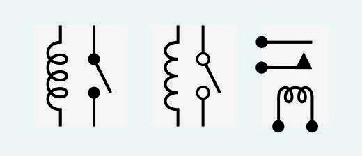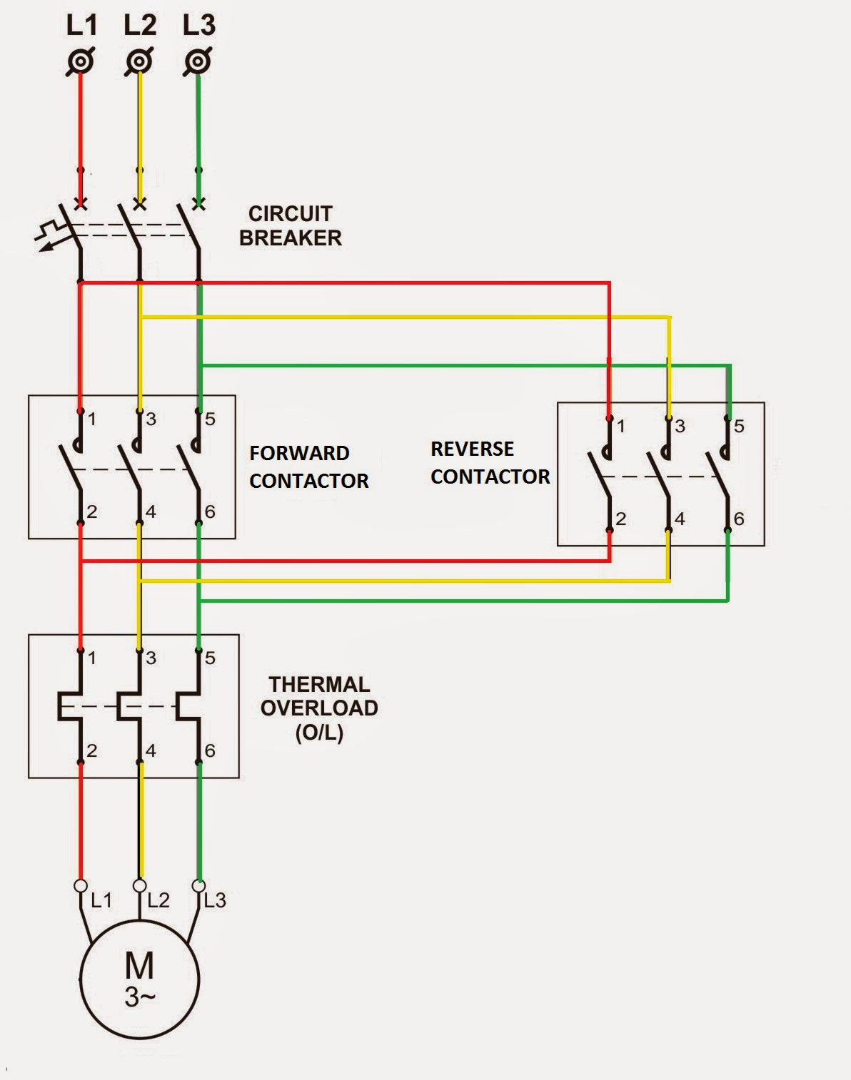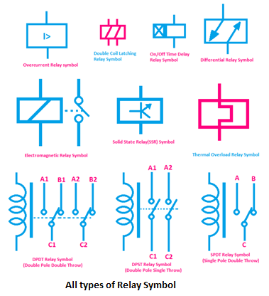
In the intricate tapestry of electrical circuits, there exist silent communicators, tiny glyphs that speak volumes to those who understand their language. These are the schematic symbols, and among them, the relay symbol holds a unique position, representing a crucial component that bridges the gap between electrical and mechanical worlds. Like a hidden hand orchestrating complex actions, the relay's symbolic representation on a diagram whispers of its powerful potential.
But what exactly is this symbol, and why is it so important? Understanding the relay’s schematic representation is akin to unlocking a secret code, allowing us to decipher the complex workings of countless electrical systems, from the simple to the sophisticated. It is a window into the very heart of automated processes, control systems, and the intricate dance of electrons that power our modern world.
The relay schematic symbol, in its various forms, has evolved alongside the technology it represents. From early depictions resembling simple switches to more nuanced representations incorporating coil and contact details, the symbol’s journey reflects the increasing complexity of relay design and functionality. This visual shorthand allows engineers and technicians to communicate efficiently, transcending language barriers and ensuring a common understanding of circuit operation.
Historically, relays were crucial for telegraphy, serving as amplifiers for weak signals over long distances. Their symbolic representation on circuit diagrams became essential for designing and maintaining these early communication networks. Today, the relay’s significance extends far beyond telegraphy, finding application in a myriad of systems, including industrial automation, power distribution, and even household appliances. The relay schematic symbol, therefore, serves as a timeless link between the historical development of this versatile component and its continued relevance in modern technology.
The interpretation of relay schematic symbols is paramount for anyone working with electrical circuits. Misunderstanding or misinterpreting these symbols can lead to faulty circuit design, malfunctioning equipment, and even safety hazards. A deep dive into the nuances of relay symbol representation, including variations based on contact type (normally open, normally closed) and coil configuration, is therefore crucial for accurate circuit analysis and design.
A relay, in essence, is an electrically operated switch. Its schematic symbol reflects this functionality. The basic symbol typically consists of a coil and a set of contacts. The coil, often represented by a rectangle or a circle, symbolizes the electromagnet that actuates the relay. The contacts, depicted as lines and arcs, represent the switching mechanism controlled by the electromagnet. Different symbols represent normally open (NO) and normally closed (NC) contacts, providing crucial information about the relay’s behavior when energized and de-energized.
Benefits of understanding relay schematic symbols include: efficient circuit analysis, accurate troubleshooting, and streamlined circuit design. For example, recognizing a normally closed contact symbol instantly tells you that the circuit is complete when the relay is de-energized, and breaks when energized.
To ensure correct implementation of relays based on their schematic symbols, always verify the contact type (NO/NC), coil voltage, and current ratings. Consult the relay’s datasheet for detailed specifications and connection diagrams.
Real-world examples of relay applications include: controlling high-voltage circuits with low-voltage signals (e.g., in industrial motor control), switching multiple circuits simultaneously (e.g., in automotive lighting systems), and providing electrical isolation between circuits (e.g., in safety-critical systems).
Advantages and Disadvantages of Relays
| Advantages | Disadvantages |
|---|---|
| Electrical Isolation | Slower Switching Speed |
| High Switching Capacity | Physical Size and Weight |
| Low Control Power | Contact Wear |
Frequently asked questions include: What is the difference between a NO and NC contact? What is the purpose of a relay coil? How do I choose the right relay for my application?
Tips for working with relay schematics: Pay close attention to contact configurations, ensure correct coil voltage and current ratings, and use a reliable component library for your design software.
In conclusion, the seemingly simple schematic symbol of a relay belies its immense importance in the world of electrical engineering. Understanding this symbolic language opens doors to a deeper understanding of circuit design, operation, and troubleshooting. From its historical roots in telegraphy to its ubiquitous presence in modern automation systems, the relay and its symbolic representation remain vital components in the ever-evolving landscape of electrical technology. By mastering the language of these silent communicators, we gain a powerful tool for shaping the technological world around us, empowering us to design, build, and maintain the complex systems that drive our modern world. Mastering relay schematic symbols is not merely an academic exercise; it's a practical necessity for anyone working with electrical circuits. This knowledge empowers you to confidently navigate the intricate world of circuit design, ensuring the seamless and safe operation of countless electrical systems.
Unlocking value in marshall county commerce
Mastering gray blue color combinations
Delhi moonrise time today live


